how to create a detailed drawing of 3d autocad part
I've been writing these tutorials on making an object in popular 3D modeling programs for a while at present, and each calendar week I've put out a phone call for what software I should do next. In that location is one constant in all those annotate threads: FreeCAD. I don't know if these suggestions reflect the popularity or difficulty of FreeCAD nevermind, it's totally the difficulty.
FreeCAD is an astonishing tool that, if used correctly, tin can exist used to make just about any office,and do information technology in a manufacturing context. If you need a bauble that'due south iii times the size of the original, FreeCAD's parametric modeling makes it easy to calibration it upwardly. If you lot're designing a thumbscrew and want the head larger while keeping the threads the same, FreeCAD is for you lot. Basically, you can think of this as a graphical extension of the Thingiverse Customizer. Very powerful, very cool, and dissimilar a lot of CAD packages out in that location,gratis.
Our in-house, overpaid SEO expert (he's really simply a monkey someone trained to employ a bullwhip) demands I link to the previous 'Making a Thing' tutorials:
- OpenSCAD
- AutoCAD Role I
- AutoCAD Part II
- Blender Office I
- Blender Part II
- SketchUp
- Autodesk 123D
The tutorial for FreeCAD continues below.
Our Affair

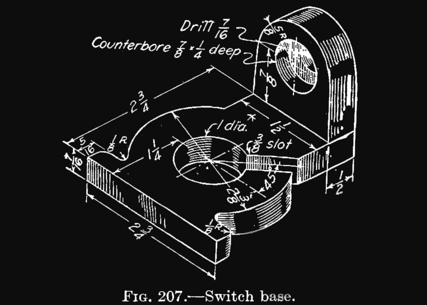
We won't be copying this thingexactly –there'south a pocket-sized taper on the tab with the counterbored pigsty – but nosotros'll get close plenty so our finished model should be functionally equivalent.
Starting Up, And An Overview
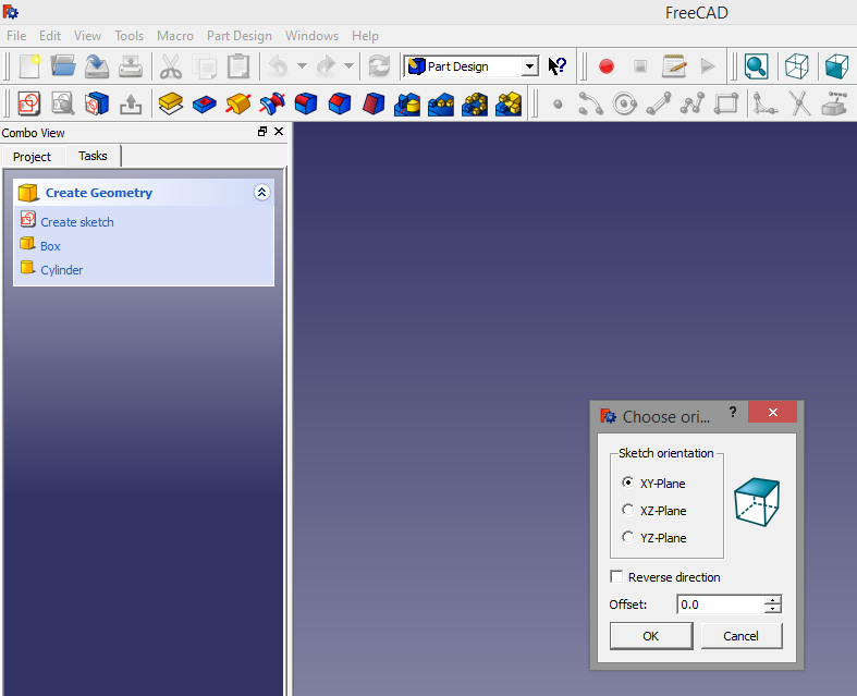
To use FreeCAD, you lot might want to download FreeCAD. It's available for Windows, Linux, and Os Ten in 32 or 64-bit varieties. Pick your poisonous substance. After downloading and installing, yous'll stop up with a "start center" that looks something like this:


Before you lot begin, y'all might also change the grid size to 1mm and turn on grid snap.
A word of note:While the grid sizesays millimeters, FreeCAD doesn't actually have units. Well, information technology has units, where 1 FreeCAD unit of measurement is equal to ane FreeCAD unit. This is fine, because now we can design our part in eighths of an inch, where one eighth of an inch is one unit of measurement. It's simpler, and to print out a correctly sized part we'll need to multiplyanyway…
If yous read nothing else, read these 2 paragraphs
FreeCAD is a parametric modeler. This ways all lines, figures, and subassemblies are defined past parameters and constraints. parameters are pieces of information that define a property of a part – a 10cm cube would have a parameter for the X, Y, and Z axes equal to 10cm. Constraints define the relationship between parts of an object. 2 lines can be constrained to beingness parallel; move one vertex of a line, and a vertex of the constrained line will motion also.
Modeling an object parametrically is how companies can pattern many similar, simply differently sized objects. A company that makes shoes may have just ane model for every size of shoe. With parametric models, fabricating the parts for a run of size 6 and size ten shoes may be every bit simple as changing a single number – the length from toe to heel.
Finally, Building
For most of our modeling, we'll exist working with two toolbars. They are the geometries andconstraints toolbars:
The Geometries toolbar is what yous would find in simply about any CAD or cartoon package. You have buttons for creating a point, an arc, a circumvolve, lines and polylines, and even fillet and trim buttons.
The Constraints toolbar has buttons for locking an object (a line, circle, polyline, or what take you) onto the vertical axis and horizontal centrality. In addition, lines can be made parallel, perpendicular, on a tangent to an arc, and the vertical, horizontal distances of a line, also as the total length of a line or the radius of a circle may be constrained as well.
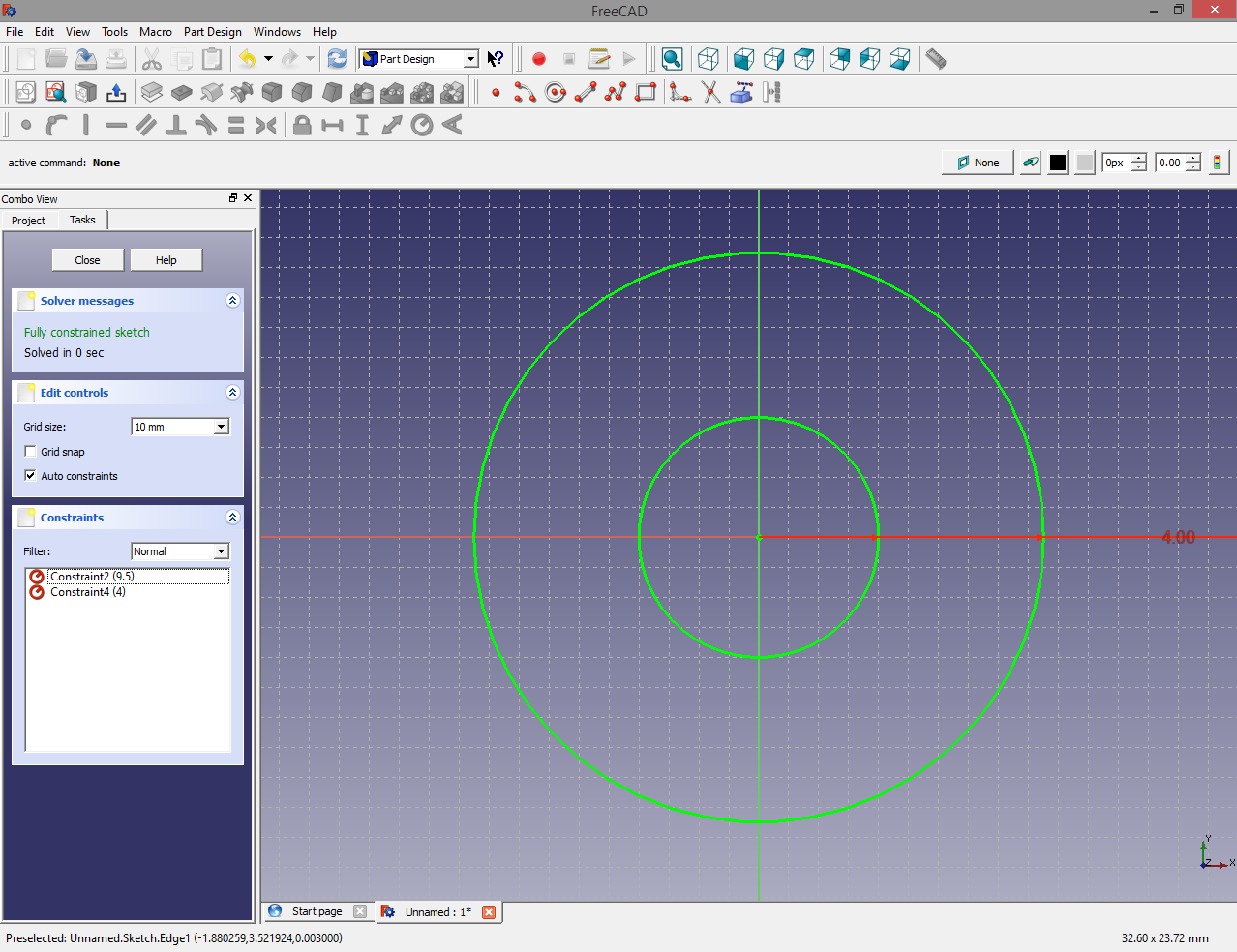
The outset part of our 'thing' we'll depict is the largest circle. Using the grid snap (or by pressing CTRL while moving the cursor effectually), draw a circle at 0,0 on the grid. This circle volition take a radius of 9.five. We're doing our units in eighths of an inch, and since the largest circle has a diameter of 2 3/viii″, or 19/8″, the radius volition be ix.5 units. Also add another circle with a radius of 4.

After yous've drawn and constrained these circles, you should have something that looks like this:

Now for some detailing

Using the Trim tool on the geometry toolbar, trim off all the excess – the ends of both lines, and the cutout on both of the circles. Now you should take something that looks like the letter C.

With the "Fix a length" constraint tool, make the altitude between both of the 45 degree lines to be 3. Finally, lock the upper, outer vertex of the slot with the 'Lock' constraint. You should have something that looks like the pic to the correct. You'll too notice on the left-mitt toolbar of FreeCAD the "Solver letters" says it's a fully constrained sketch.

This means nosotros've washed thisproperly. Well, in this case that'south a bit of a lie (we oasis't guaranteed the slot is lined up with the eye of the circles), only information technology's close enough. In FreeCAD, the object is to have a fully constrained object. That'south what we've done hither.
Since I like to keep these tutorials down to nearly 1000 words, I'grand going to terminate this hither. In the next installment of this tutorial, we're going to add the flanges on this washer-type part, extrude it into the third dimension, and add the bit with the countersunk hole.
To be continued, and I'll probably put a link to Part Ii right hither.
Source: https://hackaday.com/2014/02/05/3d-printering-making-a-thing-in-freecad-part-i/
0 Response to "how to create a detailed drawing of 3d autocad part"
Enregistrer un commentaire